Pside-Kick Installation Instructions
Step 1:
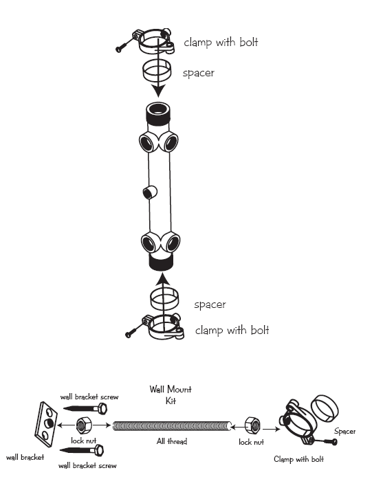
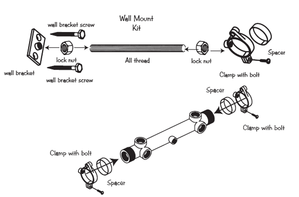
The pside-kicktm can be installed vertically, horizontally, wall stud mount, or pipe mount. Mount to Wall (If not mounting, skip to step 2.)
A) Thread two lock nuts on each all thread bolt about 2" in. Thread the wall bracket on one end of 3/8" X 6" all thread bolt and thread clamp to other end of it.
B) Attach the clamps and pvc spacers to the manifold with the bolts but do not tighten. Hold manifold to wall over a stud and mark the holes.
C) Remove clamps from manifold and use wall screws to mount wall brackets to wall stud.
Step 2:
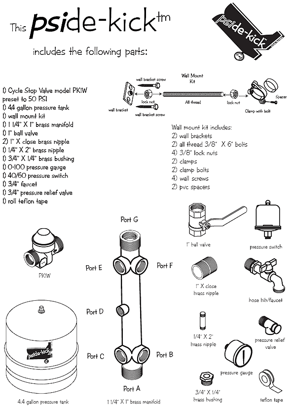
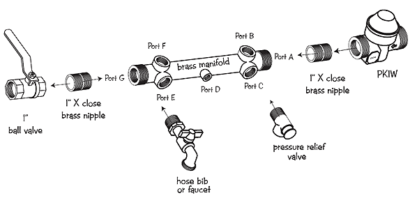
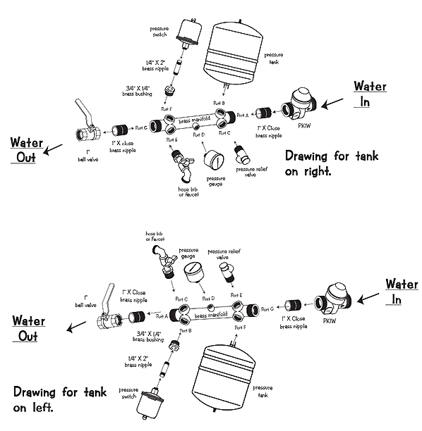
If installing the PK1W above ground, wrap threads on both ends of one of the 1" X Close nipple with 5-7 layers of teflon tape. Thread one end into Port A on the 1" brass manifold. (Note...which port will determine what side/direction the pressure tank will be situated on the manifold. These instructions are for the tank to the right. For tank to the left, see the final assembly on page 6 for drawing) If hanging the PK1W in the well, see example drawing on page 1 and skip to step 4.
Step 3:
Thread the other end of the 1" X close nipple into the PK1W discharge end. (See arrow on valve casting) Note angle of valve so that the adjustment screw under the white cap is accessible in the event any adjustments need to be made after installation.
Step 4:
Wrap threads on the pressure relief valve with 5-7 layers of teflon tape and thread into port C on the brass manifold. (Note: You will need to attach a drain hose or pipe to the pressure relief valve to direct water to a drain or outside in the event the valve ever drains pressure off the system.)
Step 5:
Wrap threads on the hose bib/faucet with 5-7 layers of teflon tape and thread into port E on the brass manifold.
Step 6:
Wrap threads on both ends of the remaining 1" X Close nipple with 5-7 wraps of teflon tape. Install one end into port G of the manifold and the other end into the 1" ball valve with handle to right. This is your isolation valve to your system and will need to be opened after testing to supply water to your system.
Step 7:
Wrap threads on the 3/4" X 1/4" brass bushing with 5-7 wraps of teflon tape and thread into port F on the brass manifold.
Step 8:
Wrap threads on both ends of the 1/4" X 2" brass nipple with 5-7 wraps of teflon tape and thread one end into the 3/4" X 1/4" brass bushing.
Step 9:
Thread the pressure switch onto the other end of the 1/4" X 2" nipple.
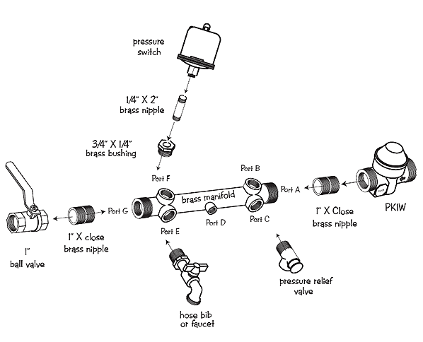
(Note: Do not install pressure tank or pressure gauge until unit has been mounted to wall)
Step 10:
Mount assembly to wall stud
A) Re-attach clamps and all thread bolts to the wall bracket. Insert the manifold with spacers into the clamps and tighten lock nuts.
B )Adjust the clamps to align port B to accommodate the pressure tank installation on the right side of the manifold. Before installing the tank, tighten the clamp bolts for stability.
Step 11:
Wrap threads of pressure tank 5-7 layers of teflon tape. Thread into port B taking care not to bend the all thread wall mount bolts.
Step 12:
Wrap threads of pressure gauge with 5-7 layers of teflon tape. Thread into port D.
Step 13:
When installing the PK1W at the well, either the 1" female or the 1 1/4" male threads on the PK1W can be used to connect to your pump system as needed. The PK1W must be installed before any water lines (including frost free hydrants) that tee off the main line prior to the pside-kicktm.
Unions can be used on either or both ends of the pside-kicktm.
This completes the assembly.
Testing the system:
The pside-kicktm should be tested before hooking it up to your system.
(Important Note: Be sure all pipe and fittings between the pump and the pside-kicktm is rated to handle the maximum pressure the pump can build at shut off or dead head.)
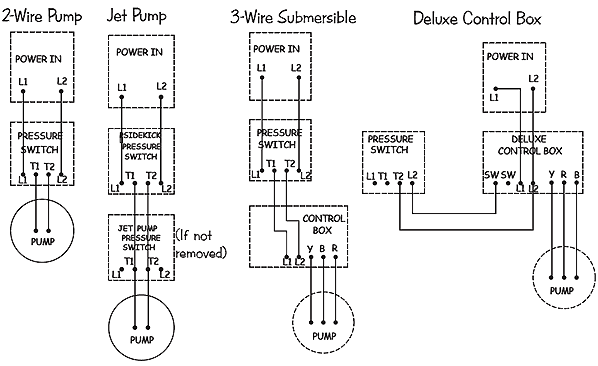
A) Before attaching pipe to the pside-kicktm, attach wire to pressure switch and pump as per pressure switch wiring diagrams below and run pump until water is clear.
B) Connect the pump discharge to the intake of the PK1W. (See direction of flow arrow on valve casting)
C) Close the 1" ball valve to isolate the pside-kicktm from your system.
D) Open the hose bib/faucet to a 2-3 gpm flow. (We recommend attaching a garden hose to the hose bib/faucet so you can control where water is going when testing the system.) Turn on the pump. (If there are any leaks, tighten fittings as necessary.)
E) Run pump until air is out of the system and check to make sure the Cycle Stop Valve is holding approximately 50 PSI and the pump does not cycle off. (The pump stays running)
F) Close the hose bib/faucet. (It should take your pump approximately 30-45 seconds to turn off at 60 PSI). After the pump turns off,, open the hose bib/faucet again to a 2-3 gpm flow. The pressure should begin to drop as the pressure tank empties. Once system pressure drops to 40 PSI, the pump should come back on. Once the pressure reaches 50 PSI, the PK1W will begin to control the pump and the pressure should stop rising and hold constant as long as a demand of more than 1 gpm is being used.
California Proposition 65 Warning: This product contains chemicals known to the state of California to cause cancer and birth defects or other reproductive harm. (Installer: California law requires that this warning be given to consumer.)
Product Specifications


